The Autocaster
An FPGA-Based Embedded System to Autonomously Play Music Video Games
The Autocaster is an embedded system based around a Digilent Atlys FPGA board, developed by Russell Joyce as a final year project for the MEng Computer Science with Embedded Systems Engineering course in 2013.
The project's original title was 'Guitar Hero on FPGA', which evolved into a system that can autonomously play both Rock Band and Guitar Hero games running on a PlayStation 3.
Source code, including build instructions, is available on GitHub at https://github.com/RTSYork/Autocaster.
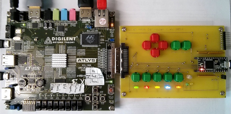
Final hardware (with PCB) - Atlys FPGA board on left, Teensy USB controller board on right
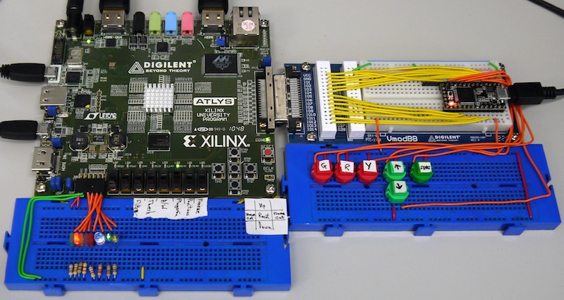
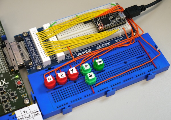
Prototype hardware - Atlys FPGA board on left, Teensy USB controller board on right
Using the System
The system is fairly straightforward to use, once programmed with the correct bitstream and software, and connected to the console. The current hardware set-up includes the bitstream on the Atlys board's flash, so will program automatically when switched on.
Before programming the system, connect the following cables:
- Micro-USB for programming the Atlys (optional)
- Micro-USB for serial UART to the Atlys (optional)
- HDMI input to Atlys from the PS3, via Component-to-HDMI converter (use HDMI IN socket at top of Atlys)
- HDMI output from Atlys to a display, works with HDMI or HDMI-to-DVI cable (use HDMI OUT socket at top of Atlys)
- Micro-USB for controller output from Teensy to PS3
Turn the PlayStation 3 and converter box on first, so an HDMI signal is already present on the FPGA's input. The PS3 must be outputting to component video at 720p for the system to recognise the HDMI connection.
Once the PS3 and converter box are on and connected, turn on the Atlys board (this will also power on the Teensy). Ensure all switches are turned off on the Atlys, to avoid triggering button presses in the PS3 menus.
If the Atlys has the project already loaded in its flash memory, the HDMI input will be mirrored to the output display and the system will be ready to use. If not, or the latest system version needs to be loaded, follow the instructions on GitHub for synthesising the XPS project, exporting to Xilinx SDK and running.
The PS3 menus can be controlled using the buttons on the PCB, or another connected controller or keyboard. The green, red, yellow, blue and orange buttons correspond to fret buttons on the guitar neck, and translate to X, O, Square, Triangle and L1 buttons on a standard PS3 controller.
Insert the game disc into the PS3, navigate to the disc icon in the 'Game' menu, and press Green/X/Enter to start the game.
Once the game has loaded, the video input will probably break, due to the brief loss of HDMI signal when it launches. To fix this (or any other visual glitches) press the red reset button or power-cycle the Atlys board, or reprogram the FPGA.
The game menus can be navigated using the controller buttons on the PCB and a song can be launched. Once a song has loaded, use the switches to enable the game player core, as shown in the table below.
The recommended setting for playing the game (with the default delay) is guitar on expert mode. On the demo PS3, there is an 'Open Day' playlist that will provide a full day of continuous music if chosen in 'Quick Play' mode.
The recommended switch positions for running the system as a demo are SW1, SW2 and SW5 on, and the others off. This will draw markers on the screen, enable the game playing logic, and automatically progress to the next song after each one ends.
Buttons and switches
The buttons and switches on the Atlys board are mapped as follows. If the image filters are enabled in hardware, SW3 to SW7 will instead enable each level of filtered output.
| Switch | Function |
|---|---|
| SW0 | Freeze the output image (does not affect player) |
| SW1 | Draw markers on video output for positions of note detectors (does not affect player) |
| SW2 | Enable the player (turn off when navigating menus manually) |
| SW3 | Continually output player status over UART |
| SW4 | Stream video over Ethernet to PC (use the EthernetStream C# program (or see /wiki/spaces/RTS/pages/35689378) to view the video feed) |
| SW5 | Automatically progress to the next song, after a delay of around 10 seconds. Also attempts to disable player when not playing a song |
| Button | Function |
|---|---|
| Up | Increase player delay (and prints delay to the UART) |
| Down | Decrease player delay (and prints delay to the UART) |
| Left | Captures and outputs a series of consecutive video sub-frames over Ethernet (use the EthernetImage C# program to receive these) |
| Right | Outputs the current video frame buffer over Ethernet (use the freeze switch first to avoid tearing) |
| Centre | Attempts to reset the VDMA core. This often results in video sync issues, which can be fixed with the FPGA reset button |
High-level Design
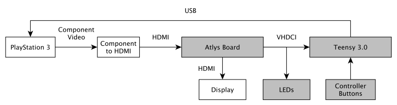
The Autocaster is based around a Digilent Atlys FPGA development board, which contains a Xilinx Spartan-6 FPGA, and has connections for HDMI video input/output, USB UART and custom peripherals.
The Atlys board is connected to the console using HDMI, allowing for a 720p image to be used for analysis by the system. Due to the HDCP encryption on the HDMI output of the PlayStation 3, a Component-to-HDMI converter is used to capture HD video. The Atlys also uses an HDMI output for connection to a display, in order to show the game screen, with possible overlays.
Control of the PlayStation 3 console is achieved using a USB connection, with a Teensy 3.0 USB development board emulating an off-the-shelf guitar controller. The Teensy is connected to the Atlys on its VHDC interface, translating control signals from the FPGA into the appropriate USB signals for sending to the console.
As well as the connection to the Teensy, the PCB has an LED for each fret button on the controller, one for the strum bar, one for the tilt sensor, and one for the most-significant bit of the whammy bar level, which can be used to view what the virtual player is currently seeing and activating.
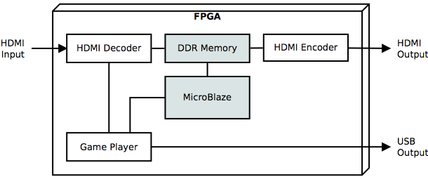
FPGA Cores
The majority of processing is performed by dedicated cores on the FPGA, including HDMI decoding/encoding, image analysis and control logic. The FPGA also contains a MicroBlaze soft processor, which is used to control the hardware.
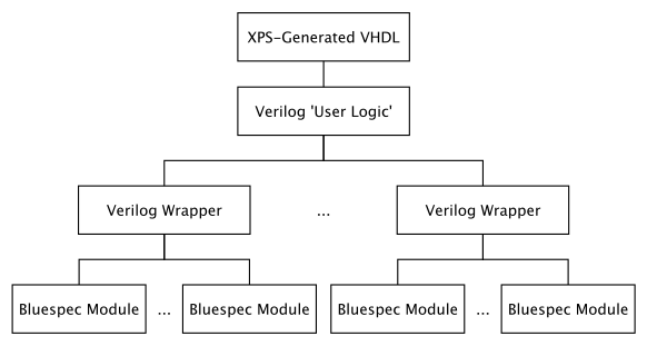
The FPGA code is written in a mixture of VHDL, Verilog and Bluespec SystemVerilog (BSV), and is based around a Xilinx Platform Studio project.
The general structure of the custom FPGA cores is as follows:
HDMI Core
The HDMI encoder/decoder core is based on the axi_hdmi core from the Digilent Atlys DSD-0000332 reference designs (available at http://www.digilentinc.com/Data/Products/ATLYS/Atlys_BSB_Support_v_3_6.zip).
The decoder modules of the core were modified to expose additional HDMI control signals, as well as making it compatible with the HDMI input from the component-to-HDMI converter unit (which always outputs HDMI with audio, rather than the DVI-style video-only signal expected by the original core).
Each frame of video is buffered in DDR-RAM, using an axi_vdma core, before being outputted to a display, allowing for image manipulation using the MicroBlaze software. Video is also streamed to the player core in real-time, so it can analyse each pixel as it is received. An optional image filter core intercepts the AXI stream bus between the HDMI and VDMA cores, in order to apply real-time image filters to the video feed.
Player Core
The gh_player core contains the image analysis and player control logic, and performs the majority of the processing required by the system.
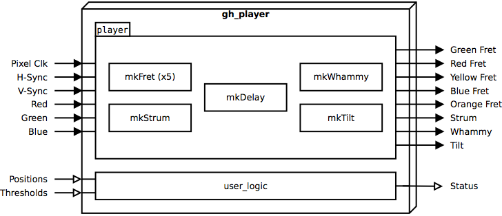
The core is defined over several files, in a mixture of VHDL, Verilog and BSV code. The top-level interface with XPS is written in VHDL, which is then linked to a Verilog module (user_logic) that controls the core's registers. The user_logic module also creates an instance of either the standard of filtered player modules, which is used to control the game.
The player module contains instances of the following BSV modules (compiled to Verilog) for low-level operation:
- mkFret (x5) - Monitors a position on the screen and outputs a signal corresponding to whether a note is present for the corresponding fret
- mkStrum - Calculates whether the strum bar needs pressing, based on the output of the mkFret modules
- mkWhammy - Constantly moves the whammy bar output (between 0->255->0) at a fixed rate
- mkTilt - Activates the tilt output at a fixed interval
- mkDelay - Adds a configurable delay to the mkFret and mkStrum outputs, allowing for detection to take place further up the screen than the target zone for playing the notes
The gh_player core has I/O ports for connection to the HDMI input (through the image_filter core) and to output pins for the Teensy and LEDs.
The player core has several software-accessible registers for controlling the following:
- Note detection thresholds
- Note detector positions
- Enabling/disabling controller output
- Switching between standard and filtered note detector
- Receiving status information about the current player state (e.g. what notes are detected)
These registers are accessed from MicroBlaze code using the functions in the gh_player driver C file.
Image Filter Core
The image filter core applies real-time image filtering to the video input, allowing for pre-processing before the image is received by the player core. The image_filter core intercepts the AXI stream bus connecting the axi_hdmi core and axi_vdma cores, in order to modify the image being written to RAM (for the monitor output), as well as the image data stream being received by the gh_player core.
The following filters are applied, based on the results of offline image analysis work:
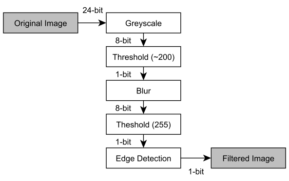
The image filter core is not enabled by default (this can be controlled from the MicroBlaze code) as it currently reduces the accuracy of the system. However, with further work the image filters could potentially improve the system accuracy by reducing interference from other graphical elements on the game screen.
The image filter core has software-accessible registers for enabling it and setting the desired level of filtering for processing and display, as well as controlling certain filter parameters. These registers are accessed from MicroBlaze code using the functions in the image_filter driver C file.
Screen Detector Core
This core allows for certain pixels to me monitored on the screen, in order to detect certain events within a game, such as a song finishing. This can be used to automatically progress to the next song after one song has finished, via MicroBlaze control logic.
MicroBlaze Software
A MicroBlaze soft core processor is used to control the main FPGA cores, through the use of software-accessible registers. This allows for tuning of parameters and modifications to certain elements of the system operation without the need to resynthesise hardware. The MicroBlaze software is written in C, using the Xilinx SDK.
The software consists of several components, each controlling a different aspect of the system. The main program initialises the hardware, including the HDMI connections and player core, then waits in a loop monitoring the buttons and switches on the Atlys board and responding to changes appropriately.
main.c
Performs the setup of the player core, and calls functions to set up the rest of the hardware.
Thresholds for note detection are defined here.
Contains definitions of what switches do, and function for drawing crosses on video buffer.
timer.c
Contains functions for controlling the hardware timer.
Not currently used (no timer implemented on theFPGA).
interrupts.c
Contains functions for setting up global interrupts.
ethernet.c
Sets up and controls the Ethernet core.
hdmi/hdmi.c
Functions for controlling HDMI core output resolution.
hdmi/edid.c
Contains functions and interrupt controller for sending EDID over I2C bus.
The EDID used is defined in the header file.
hdmi/vdma.c
Sets up VDMA core for reading and storing data from HDMI.
This file performs the majority of what is required to receive and transmit HDMI video in the system.
gpio/bitops.h
Helper functions for bit operations.
gpio/buttons.c
Handles Atlys button press interrupts.
Contains and defines any parts of the system that can be modified by button presses. This currently includes note locations and player delay value.
gpio/switches.c
Basic input functions for Atlys switches.
gpio/leds.c
Basic output functions for Atlys LEDs.
Teensy Software
The Teensy controls the USB output of the system, translating basic signals from the FPGA to an output that is recognised by the PlayStation 3 console. The Teensy software is written in C and C++, using the Arduino IDE with Teensyduino extensions and a custom USB device type.
The software polls each Teensy input pin around 200 times per second, and outputs the appropriate controller state data over the USB connection. Inputs to the Teensy are updated 60 times per second (once per frame) by the FPGA.
The emulated controller is based on the guitar bundled with Guitar Hero Warriors of Rock, using the same VID, PID, product name and manufacturer name, but with a slightly altered USB descriptor to remove the proprietary endpoints used for communication with the PS3. This causes the device to display as a standard USB game controller on a PC, while still being recognised as a guitar controller by the PS3.
The following table shows the mapping of Teensy pins to controller buttons:
| Pin | Button |
|---|---|
| 0 | Orange fret |
| 1 | Blue fret |
| 2 | Yellow fret |
| 3 | Red fret |
| 4 | Green fret |
| 5 | Up (strum) |
| 6 | Select button |
| 7 | Left |
| 8 | Start button |
| 9 | Right |
| 10 | Down |
| 14 | Whammy bar 0 (LSB) |
| 15 | Whammy bar 1 |
| 16 | Whammy bar 2 |
| 17 | Whammy bar 3 |
| 18 | Whammy bar 4 |
| 19 | Whammy bar 5 |
| 20 | Whammy bar 6 |
| 21 | Whammy bar 7 (MSB) |
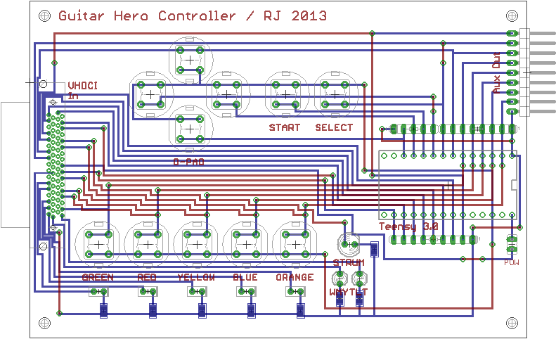
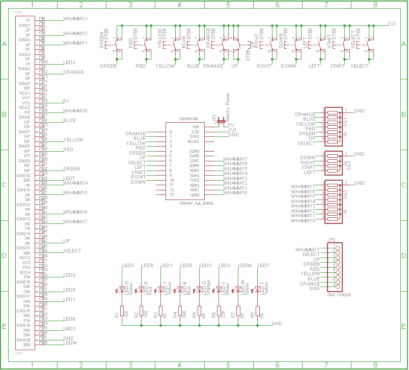
Hardware PCB Design
The physical hardware of the system consists of a single PCB connected to the VHDC interface of the Atlys, with the Teensy board mounted on it. The main function of this is to supply a connection between the Atlys and Teensy boards. It is also used to allow input from the user, and to output the status of the system using coloured LEDs.
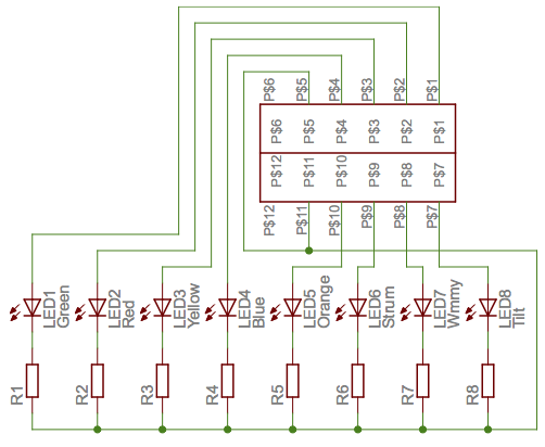
Each LED represents an output from the player core, which are independent of the actual control outputs (i.e. they will still light when the player is disabled, and aren't delayed). The first five LEDs are coloured like the fret buttons on the guitar controller, and each lights up whenever the system detects that its respective button should be pressed. The sixth LED is white and represents the strum bar output, the seventh is green and represents the most significant bit of the whammy output, and the eighth is yellow and represents the tilt control output. The buttons on the PCB can be used to control the PS3 system independently of the FPGA.
The jumper on the PCB marked POW is used to connect a 5V power supply to the Teensy from the Atlys board, allowing it to be powered with the rest of the system rather than through its USB connection. Before connecting this jumper, ensure that the 5V USB power pads have been cut on the Teensy, as described at http://www.pjrc.com/teensy/external_power.html.
The Aux Out pins on the PCB can be used to connect an external controller instead of the Teensy board, and have the following connections:
| Pin | Connection |
|---|---|
| 1 (top) | Whammy MSB |
| 2 | Tilt |
| 3 | Strum |
| 4 | Green fret |
| 5 | Red fret |
| 6 | Yellow fret |
| 7 | Blue fret |
| 8 | Orange fret |
| 9 (bottom) | Ground |
The PCB design is shown below, with Eagle design file available in the project Git repository.

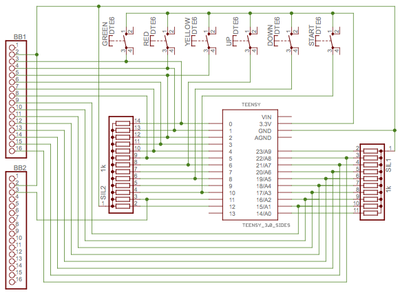
Prototype Hardware
Before the PCB was manufactured, a series of breadboards were used to connect the Teensy, buttons and LEDs to the Atlys. Details of this set-up are included to assist with replicating the system without requiring a custom PCB. The hardware is connected to two I/O interfaces of the Atlys board: the VHDCI and the Pmod connector.
The VHDC interface is connected to a VmodBB breadboard, which has the Teensy mounted on it. A second breadboard is connected to this, allowing for manual control of the PlayStation 3.
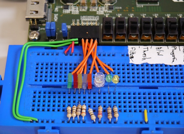
The Pmod connector is attached to eight coloured LEDs, mounted on a breadboard, with each representing a control output from the player core. The first five LEDs are coloured like the fret buttons on the guitar controller, and each lights up whenever the system detects that its respective button should be pressed. The sixth (white) LED shows the strum bar output, the seventh (green) shows the most significant bit of the whammy output, and the eighth (yellow) shows the tilt control output.
Videos
Final hardware playing expert guitar on 'No One Knows' in Rock Band 3
Note the fret and strum LEDs in the bottom-right.
https://www.youtube.com/watch?v=Ft1ZcDF2G_4
Prototype hardware playing 'Walk of Life' in Rock Band 3
https://www.youtube.com/watch?v=UUfg4A06rv8
Prototype hardware demonstration of real-time image filtering
https://www.youtube.com/watch?v=UuAydnhE_rk