Zybo VGA Output
The VGA hardware and software was last updated on 14/03/2017. Specific changes can be seen on GitHub.
SDK Run Configuration
When using the VGA core, you should use the following SDK feature to reset and program the FPGA whenever you run your software, in order to properly reset the hardware as well as the software:
Under Run -> Run Configurations, click your current Run Configurations on the left and enable options to "Reset the entire system" and "Program the FPGA".
This also removes the need to separately program the FPGA in either Vivado or SDK.
The Zybo has a VGA connector on the top-left of the board, which provides a simple 16-bits-per-pixel (5 red, 6 green, 5 blue) display output from the SoC.
Images are displayed from a frame buffer in DDR, using a number of components in the FPGA logic to generate the VGA colour and sync signals.
All the files mentioned below can be found on GitHub - you can download them in a zip file from https://github.com/RTSYork/zybo-vga/archive/master.zip.
Adding VGA to a Vivado Design
In order to use the VGA output, a number of Xilinx and Digilent IP cores need to be added to your IP design, and connected up to the correct pins on the FPGA package.
Referencing the repository for Digilent cores
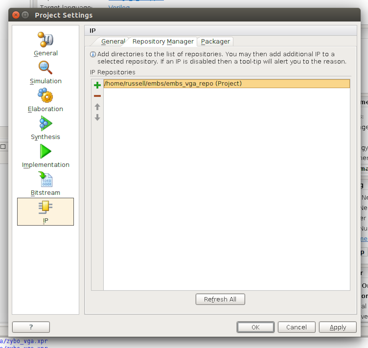
In Vivado, open the "Project Settings" screen (button in the top-left), choose the "IP" pane, and select "Repository Manager".
From here, click the +, then select the hardware/zybo_vga_repo folder from the repository. Vivado should find two IP cores in this repository.
If Vivado displays an error and can't find any cores in the repository, and you extracted the files to within your Vivado project directory, try moving the repository to another folder outside your project.
Adding the IP cores using a TCL script
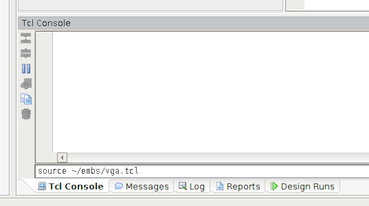
To automatically add the cores to your project, set up their options and make the appropriate connections, a Tcl script is provided in the VGA repository (hardware/zybo_vga.tcl).
To run this script, you need to source it from the Vivado Tcl console (at the bottom of the block design window), using the command: source <path to repo>/hardware/zybo_vga.tcl (as below).
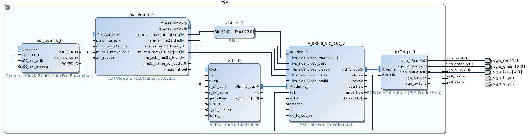
After running this script, the following (currently unconnected) hierarchy should exist in your block design (use the +/- in the top left to expand and collapse a hierarchy block in Vivado).
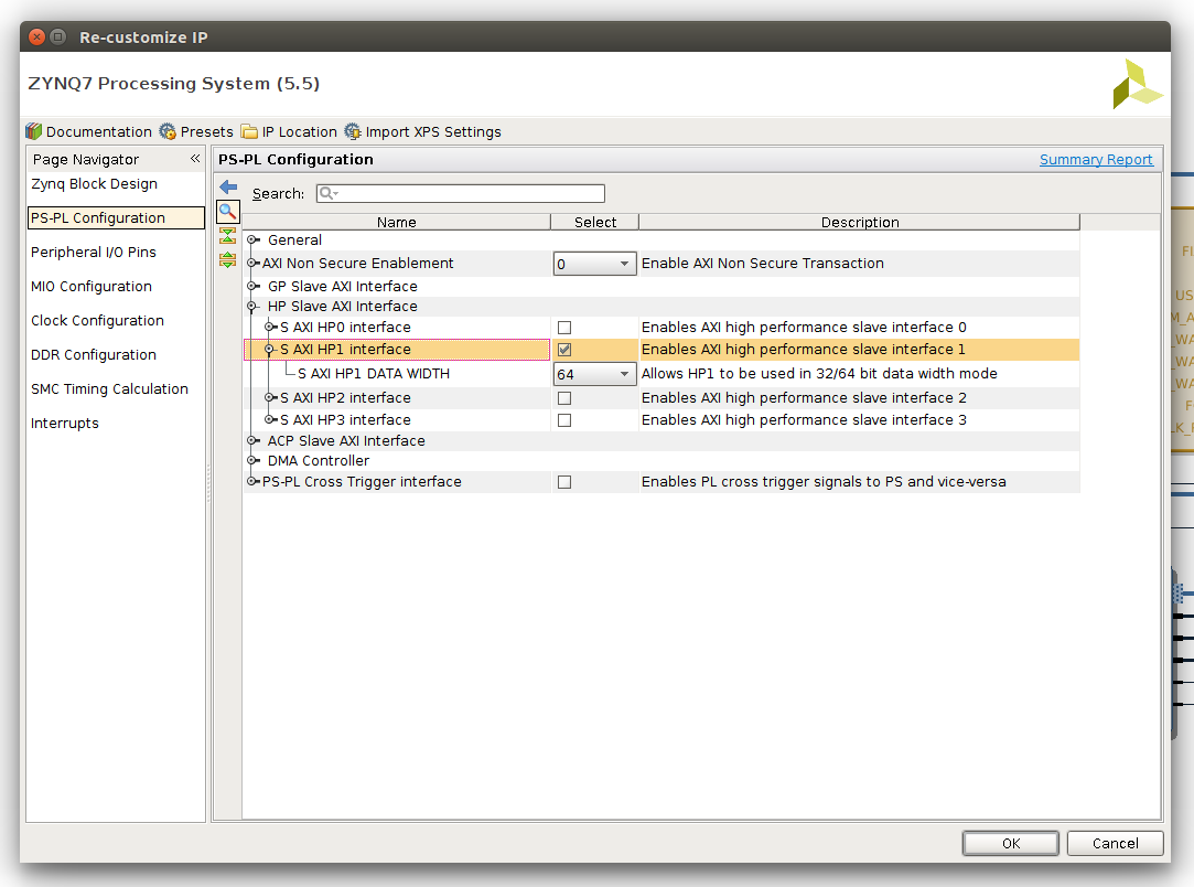
The VGA output uses DMA to copy data directly from the DDR. To allow this, you will need to enable a high-performance AXI slave port on the Zynq Processing System.
As we are using S_AXI_HP0 /wiki/spaces/RTS/pages/35689890, using S_AXI_HP1 for the VGA will give the best performance, and avoid adding unnecessary additional bus logic to the FPGA fabric.
To enable S_AXI_HP1, double-click on the ZYNQ7 Processing System block, select "PS-PL Configuration", expand "HP Slave AXI Interface", tick "S AXI HP1 Interface" (as below), and click OK.
Once the HP Slave has been enabled, click the "Run Connection Automation" prompt at the top of your block design to automatically connect up the AXI master and slave ports to the Processing System, and to assign addresses. When prompted, ensure S_AXI_HP1 is selected.
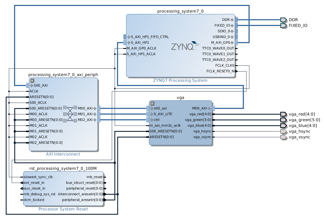
The resulting block design should look similar to the following:
Adding the VGA output pin constraints
To connect the external VGA pins from the block design to the correct physical pins on the Zybo board, a set of pin constraints (from hardware/zybo_vga.xdc) needs to be added to your Vivado project.
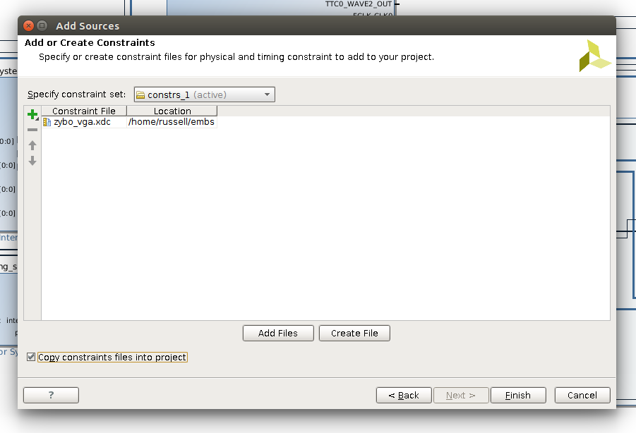
To do this, open your block design and select File, Add Sources. Choose "Add or create constraints" and click Next. Ensure "constrs_1" is selected as the constraint set, then click Add Files, and select hardware/zybo_vga.xdc from the VGA repository. Ensure that "Copy constraint files into project" is ticked, and click Finish.
The hardware design should now be ready for synthesis, implementation, and exporting to SDK.
Using VGA from Xilinx SDK
The VGA hardware uses two frame buffers in DDR to output images from. You may want to use the second frame buffer for smoother transitions between images, as switching is instantaneous, or to hold a completely separate second image.
Data is stored in the frame buffer using 32 bits per pixel. Each colour component takes one byte, with the highest byte unused, followed by red, blue and green. This gives a pixel format of 0x00RRBBGG.
As the physical hardware of the Zybo only supports outputting 16-bit colour values, the lowest three bits of red and blue, and the lowest two bits of green are ignored.
Remember to flush the caches after changing the frame buffer, so data is written back to DDR for the hardware to use. If writing the entire buffer, completely flushing the caches with Xil_DCacheFlush() will be more efficient than flushing a region, as the caches are significantly smaller than the frame buffer.
Adding the software drivers
The drivers for the Xilinx VDMA and VTC cores should be added to your BSP project automatically (if they're not, try recreating the BSP), but additional drivers are required for the Digilent cores.
To add these into your SDK project, drag the software/zybo_vga folder from the repository into the src folder of your application project within the SDK window, and #include zybo_vga/display_ctrl.h in your source.
Controlling the VGA output from C
The VGA display driver is set up in a similar way to other IP cores, using a struct of type DisplayCtrl (defined in zybo_vga/display_ctrl.h).
The functions in display_ctrl.h can be used to initialise the display controller, start and stop the output, change the current frame buffer, and set the output resolution.
These functions are documented in the library source code, and vga_example.c shows how to set up the output and display a basic gradient on the screen.
Possible output resolutions are in zybo_vga/vga_modes.h - the widescreen monitors in the hardware labs work well with a 1440x900 resolution.
Higher resolutions than this are possible (e.g. 1680x1050), but require the master interface of the AXI VDMA core to be clocked faster than default (125MHz should work).
Smooth frame transitions
When creating animations, smooth transitions between frames can be achieved by writing to the back buffer (the currently inactive frame), then switching to it with DisplayChangeFrame().
This function will return immediately, but the DisplayWaitForSync() function can then be used to synchronise with the frame output, so the active buffer is never directly written to. This function will block until the frame specified with DisplayChangeFrame() is actually being shown.
An example of this can be seen in vga_example_anim.c.