Zybo Z7 HDMI Output
The Zybo Z7 has an HDMI output (TX) connector on the top-left of the board, which provides a simple 24-bits-per-pixel (8 red, 8 green, 8 blue) display output from the SoC.
Note that there is also an HDMI input (RX) connector on the top-right of the board. Ensure you plug the cable into the output and not this.
Images are displayed from a frame buffer in DDR, using a number of components in the FPGA logic to generate the HDMI/DVI graphics and associated signals.
All the files mentioned below can be found in a repository on GitHub - you can download the latest version in a zip file from https://github.com/RTSYork/zybo-z7-hdmi/archive/master.zip.
Either clone or download and unzip this repository to a location outside of your Vivado project directory before proceeding with the following steps. You only need to do this once, unless we update the files.
Adding HDMI output to a Vivado Design
In order to use the HDMI output, a number of Xilinx and Digilent IP cores need to be added to your block design, and connected up to the correct pins on the Zynq SoC package.
Referencing the repository for Digilent IP cores
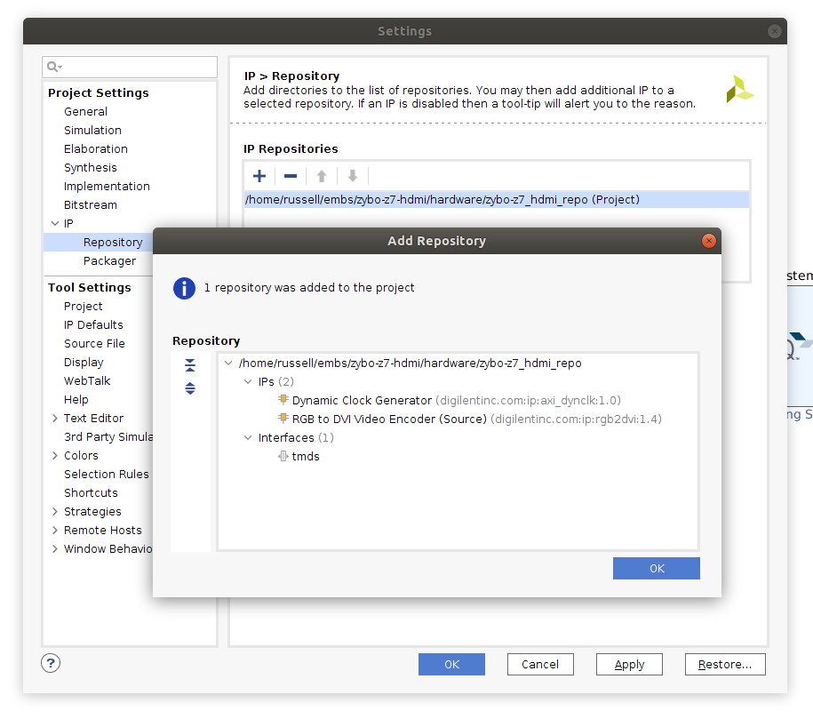
In Vivado, open the "Settings" screen (button in the top-left of the screen with the gear icon), expand the "IP" option under "Project Settings", and select the "Repository" pane.
From here, click the + under "IP Repositories", then select the hardware/zybo_z7_hdmi_repo folder from the downloaded HDMI repository. Vivado should find two IP cores and one interface definition in this repository (see the screenshot below).
If Vivado displays an error and can't find any cores in the repository, and you extracted the files to within your Vivado project directory, try moving the repository to another folder outside your project.
Adding the IP cores using a Tcl script
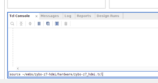
To automatically add the necessary cores to your project, set up their options and make the appropriate connections, a Tcl script is provided in the HDMI repository (hardware/zybo_z7_hdmi.tcl).
To run this script, you need to source it from the Vivado Tcl console (at the bottom of the block design window), using the command: source <path to repo>/hardware/zybo_z7_hdmi.tcl (as below).
Ensure you already have a 'ZYNQ7 Processing System' block in your design before sourcing this script or it will fail.
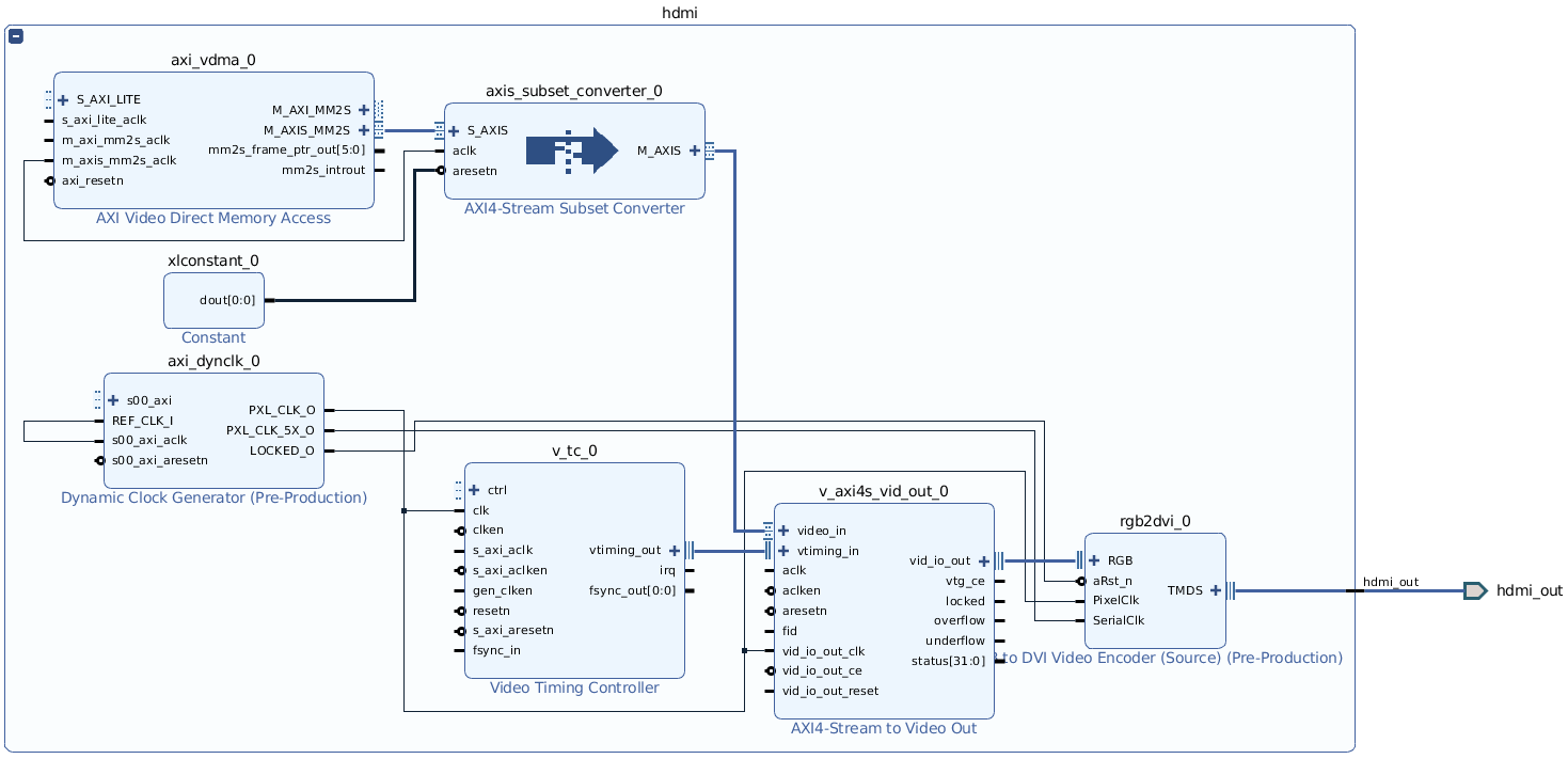
After running this script, the following (currently unconnected) hierarchy should exist in your block design (use the +/- in the top left to expand and collapse a hierarchy block in Vivado).
The HDMI output uses DMA to copy data directly from the DDR. To allow this, you will need a high-performance AXI slave port on the Zynq Processing System.
As we are using S_AXI_HP0 /wiki/spaces/RTS/pages/35689890, using S_AXI_HP1 for the HDMI will give the best performance, and avoid adding unnecessary additional bus logic to the FPGA fabric.
The script should enable this interface for you, but from this point on you will need to be careful in connection automation dialogs to ensure that the HDMI and HLS components use the correct interfaces.
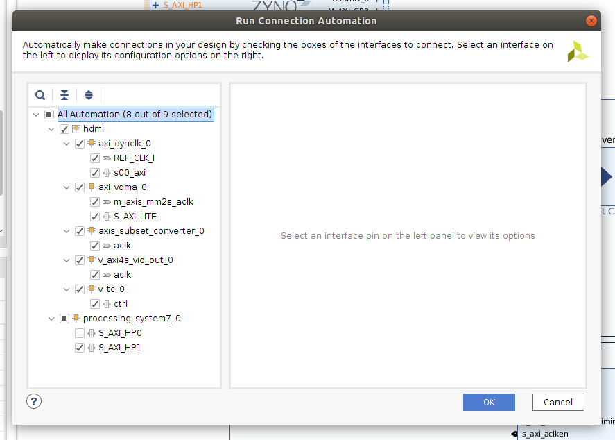
Next, click the "Run Connection Automation" prompt at the top of your block design to automatically connect up the AXI master and slave ports to the Processing System, and to assign addresses.
The default values are usually sensible, but ensure that S_AXI_HP1 is selected as the processing_system7_0 interface (see screenshot).
The resulting block design should look similar to the following. The tools should have also created an AXI SmartConnect IP within the HDMI block for the HDMI's master interface, and assigned appropriate addresses for all the cores.

Adding the HDMI output pin constraints
To map the external HDMI pins from the block design to the physical pins of the SoC that connect to the HDMI TX port on the Zybo Z7 board, a set of pin constraints (from hardware/zybo_z7_hdmi.xdc) needs to be added to your Vivado project.
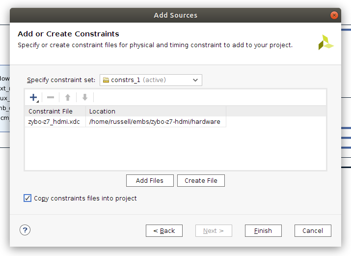
To do this, open your block design and select File, Add Sources. Choose "Add or create constraints" and click Next. Ensure "constrs_1" is selected as the constraint set, then click Add Files, and select hardware/zybo_z7_hdmi.xdc from the HDMI repository. Ensure that "Copy constraint files into project" is ticked, and click Finish.
The hardware design should now be ready for synthesis, implementation, and exporting to Vitis.
Using HDMI output in Vitis
The HDMI hardware uses two frame buffers in DDR to output images from. You may want to use the second frame buffer for smoother transitions between images, as switching is instantaneous, or to hold a completely separate second image.
Data is stored in the frame buffer using 32 bits per pixel. Each colour component takes one byte, with the highest byte unused, followed by red, blue and green. This gives a pixel format of 0x00RRGGBB.
Remember to flush the caches after changing the frame buffer, so data is written back to DDR for the hardware to use. If writing the entire buffer, completely flushing the caches with Xil_DCacheFlush() will be more efficient than flushing a region, as the caches are significantly smaller than the frame buffer.
Adding the software drivers
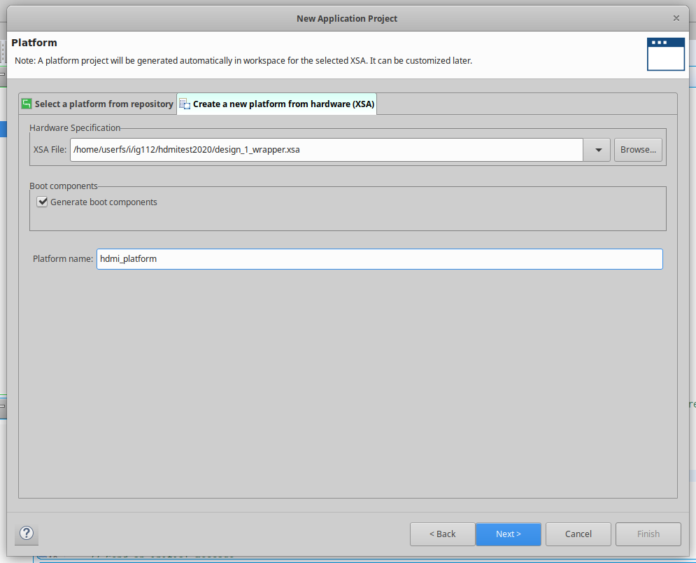
Import your new hardware and create a Hello World application on it.
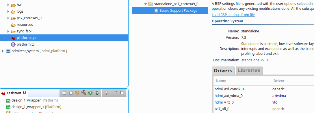
The drivers for the Xilinx VDMA and VTC cores should be added to your System automatically. You can check this by opening the platform.spr file.
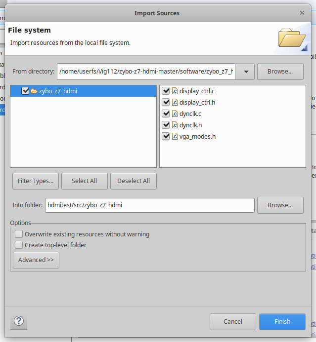
However additional drivers are required for the Digilent cores. Right click the src folder in your application project and select Import Sources. Import the software/zybo_z7_hdmi/ files into a folder called zybo_z7_hdmi.
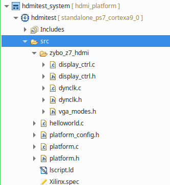
Now add #include zybo_z7_hdmi/display_ctrl.h in your source and you are ready to go.
Controlling the HDMI output from C
The HDMI display driver is set up in a similar way to other IP cores, using a struct of type DisplayCtrl (defined in zybo_z7_hdmi/display_ctrl.h).
The functions in display_ctrl.h can be used to initialise the display controller, start and stop the output, change the current frame buffer, and set the output resolution.
These functions are documented in the library source code, and hdmi_example.c shows how to set up the output and display a basic gradient on the screen.
Possible output resolutions are in zybo_z7_hdmi/vga_modes.h - the widescreen monitors in the hardware labs work well with a 1440x900 resolution (this is fine for EMBS).
Higher resolutions than this are possible (e.g. 1680x1050), but require the master interface of the AXI VDMA core to be clocked faster than default (125MHz should work).
Smooth frame transitions
When creating animations, smooth transitions between frames can be achieved by writing to the back buffer (the currently inactive frame), then switching to it with DisplayChangeFrame() during the vertical blanking interval.
This function will return immediately, but the DisplayWaitForSync() function can then be used to synchronise with the frame output, so the active buffer is never directly written to. This function will block until the frame specified with DisplayChangeFrame() is actually being shown.
An example of this can be seen in hdmi_example_anim.c. You can check the display is running at 60 frames per second by adding a timer to the C code (or approximately by just counting pixels and using a stopwatch).